By Richard | 09 May 2020 | 0 Comments
CGMB Infrared Diode Operation Instructions
CGMB Infrared Diode Operation Instructions
Please follow the steps below:
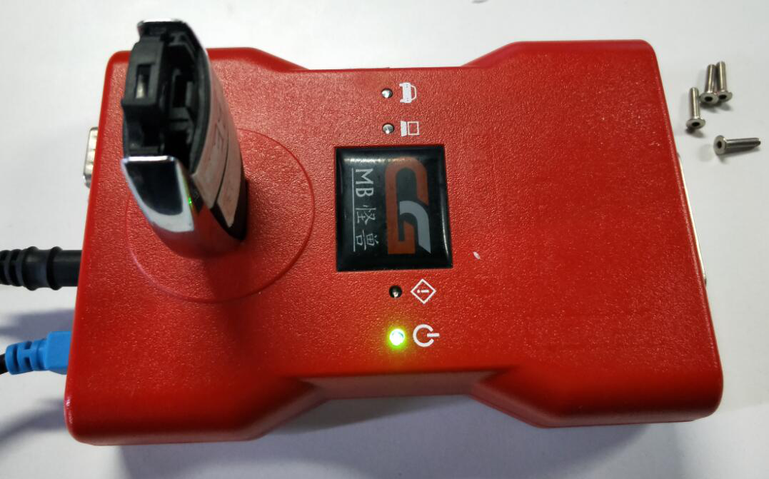
1. Device function check :Before operation,please be sure that the device is in a normal working state that could read key successfully;
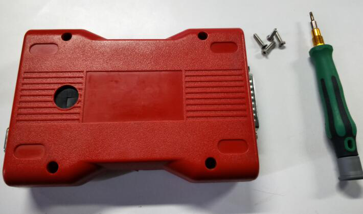
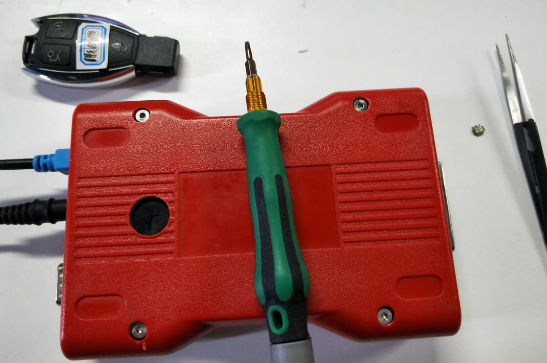
Next to disconnect the USB and 12V power supply and ready to disassemble the CGDI MB shell, as shown picture below: (Note: Use a suitable Allen screwdriver, do not use brute force to prevent the screw from sliding, the removed screws are stored)
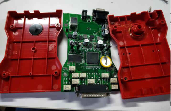
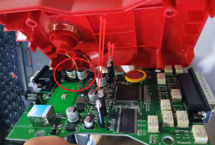
2.Open the enclosure of the device : Open the device shell gently by hand, as shown picture below: (Note: Do not force to open it to prevent the wire of the induction coil from being torn off!)
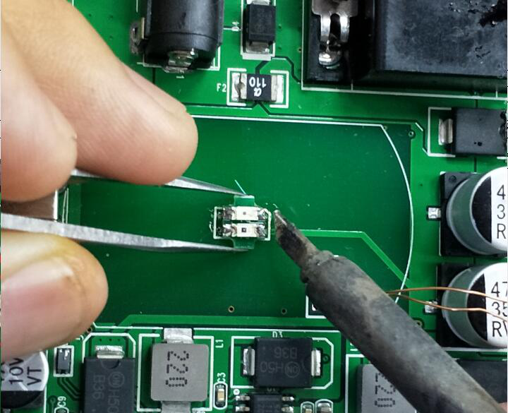
 3. Take the original infrared Diode : Use a soldering iron to add tin on both sides of the old infrared device, drag it after heating, and then remove the old infrared device, as shown below: (The temperature of the soldering iron should not be too high, the time should not be too long, to prevent long-term heating damage to the PCB board, certain Welding capacity)
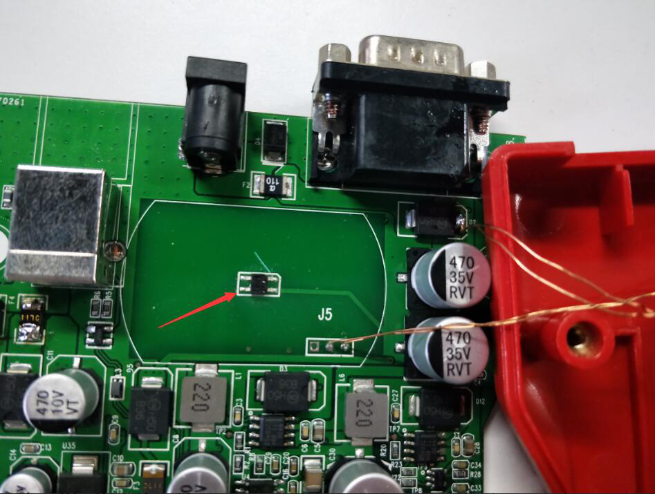
4. Place a new infrared board. Use a soldering iron to flatten the original pad with a soldering iron, and then use tweezers to place the new infrared board on the original pad
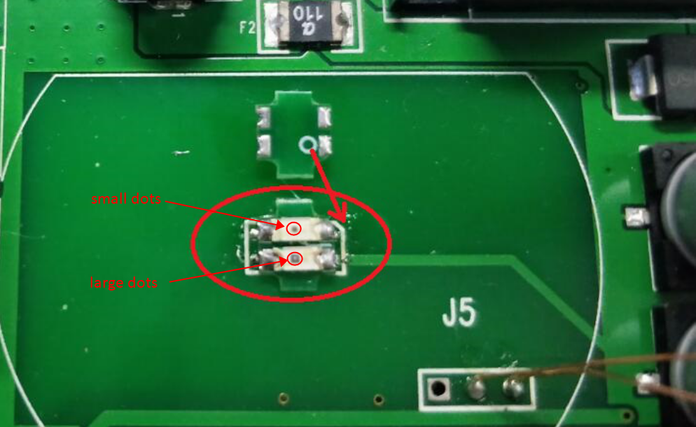
as shown in the figure, as shown below: (Infrared has a direction, the bottom 1 foot circle is aligned with the missing corner on the PCB Where there are small dots above and large dots below)
 5. Weld new infrared board. Hold the new infrared board with tweezers, and solder the four feet with a soldering iron, as shown below: (The temperature of the soldering iron should not be too high, the time should not be too long, to prevent long-term heating damage to the infrared lamp, observe the pins after soldering , There can be no tin short circuit and virtual soldering, and a certain welding capacity is required)
6. Install the top shell. After welding, buckle the upper shell and PCB board, as shown below:
Note: (1) Note that the four indicator LEDs must be aligned with the holes;
(2) The wires of the induction coil should be arranged well, and cannot fall into the infrared induction area to prevent it from blocking the infrared transceiver;
(3) Do not use brute force to buckle the shell, you must confirm the two steps above and then close the cover.
 7. Test function : Please do not tighten the screws after closing the cover. At this time need to plug USB and 12V to read a key with all direction. If software shows that read successfully,then you could start to tighten screws .As shown in the figure below: (Do not tighten the screws before the reading is successful)
8. Install the bottom case : Put the four previously removed screws into the back shell and tighten with a screwdriver. The replacement operation is all completed! As shown below:
Please follow the steps below:
1. Device function check :Before operation,please be sure that the device is in a normal working state that could read key successfully;
Next to disconnect the USB and 12V power supply and ready to disassemble the CGDI MB shell, as shown picture below: (Note: Use a suitable Allen screwdriver, do not use brute force to prevent the screw from sliding, the removed screws are stored)

2.Open the enclosure of the device : Open the device shell gently by hand, as shown picture below: (Note: Do not force to open it to prevent the wire of the induction coil from being torn off!)
 3. Take the original infrared Diode : Use a soldering iron to add tin on both sides of the old infrared device, drag it after heating, and then remove the old infrared device, as shown below: (The temperature of the soldering iron should not be too high, the time should not be too long, to prevent long-term heating damage to the PCB board, certain Welding capacity)
4. Place a new infrared board. Use a soldering iron to flatten the original pad with a soldering iron, and then use tweezers to place the new infrared board on the original pad
as shown in the figure, as shown below: (Infrared has a direction, the bottom 1 foot circle is aligned with the missing corner on the PCB Where there are small dots above and large dots below)
 5. Weld new infrared board. Hold the new infrared board with tweezers, and solder the four feet with a soldering iron, as shown below: (The temperature of the soldering iron should not be too high, the time should not be too long, to prevent long-term heating damage to the infrared lamp, observe the pins after soldering , There can be no tin short circuit and virtual soldering, and a certain welding capacity is required)
6. Install the top shell. After welding, buckle the upper shell and PCB board, as shown below:
Note: (1) Note that the four indicator LEDs must be aligned with the holes;
(2) The wires of the induction coil should be arranged well, and cannot fall into the infrared induction area to prevent it from blocking the infrared transceiver;
(3) Do not use brute force to buckle the shell, you must confirm the two steps above and then close the cover.
 7. Test function : Please do not tighten the screws after closing the cover. At this time need to plug USB and 12V to read a key with all direction. If software shows that read successfully,then you could start to tighten screws .As shown in the figure below: (Do not tighten the screws before the reading is successful)
8. Install the bottom case : Put the four previously removed screws into the back shell and tighten with a screwdriver. The replacement operation is all completed! As shown below:

Leave a Reply
Your email address will not be published.Required fields are marked. *